HPR 010 Mono: Very Slow Build

Collapse
X
 
  • Time
  • Show
Clear All
new posts
  • boredom.is.me
    Senior Member
    • Jun 2009
    • 595

    #31
    The mount is slowly evolving. That's the good thing about being able to make parts yourself. If the overall idea shifts, you can just make new parts. I brought the side bolts closer together (24mm to 16mm) due to possible clearance issues. The inner hole was increased from 13mm to 18mm to accommodate even larger thrust bearings for 6mm shafts. I replaced the cooling vents with another set of mounting holes. This will allow the motor to be clocked at 45 degree intervals instead of just 90. I also do not like the idea of only using two bolts, so I kept all four. I also made the angle adjustable from 10 to 30 degrees. That should be plenty.

    I would like to play around with the idea of water cooling the entire circle instead of just the top edge like all of the other cheesy mounts. The unfortunate part is that it would compromise the overall strength of the mount. The only reason I went with 1/4" was to allow for the use of m4 side bolts.

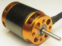
    The motors you see are the FC3730 (larger outrunner), 4082 with a 60mm long jacket, and the smaller HF500 (closer to the Scorpion's size). For reference, the mount with the twin outrunners have 3/16" side plates, while the inrunner/outrunner mount has 1/8" side plates.

    As I was making this post, I came up with the last design. No water cooling, but a lot of through holes. It shouldn't compromise strength at all. I can also bevel the edges on one side. (I don't really want to try a two sided bevel again with this machine.)
    Attached Files

    Comment

    • axel
      Senior Member
      • May 2007
      • 127

      #32
      careful if you ordered the 3730-3 it has 1580 KV

      check the manufacturer spec

      Comment

      • boredom.is.me
        Senior Member
        • Jun 2009
        • 595

        #33
        Yes I understand. That's why I had it as "1850kv". It's just a typo on the site. Thank you again though.

        Comment

        • boredom.is.me
          Senior Member
          • Jun 2009
          • 595

          #34
          Here is the new motor mount face. As much as I really like the old style, the new one actually looks pretty good. It's a lot prettier in person than in CAD. The overall quality of the cut is significantly better too. It is a little heavier, 39.6g vs 37.7g. I also cut it with a vertical grain instead of horizontal like the old one.

          I wanted to make the side drill jig, but my buddies called me to play a game... That will happen tomorrow.

          What's wierd is that my plunge/drill operations do not go all the way through unless I exagerate the depth. In normally leaves a slight skin which you can see in the picture.

          The first set of holes was me being stupid. I didn't zero the x a is to a good location. The design was hanging 2mm off of the material.

          I really would like to build a vibrating/tumble polisher, then have the parts anodized, but that's a bit more than I want to do at this given moment.
          Attached Files

          Comment

          • srislash
            Not there yet
            • Mar 2011
            • 7673

            #35
            That looks like a great mount. Going good sir!

            Comment

            • boredom.is.me
              Senior Member
              • Jun 2009
              • 595

              #36
              Now I just have to make the side plates. I want to make them out of 4mm carbon.
              Attached Files

              Comment

              • boredom.is.me
                Senior Member
                • Jun 2009
                • 595

                #37
                Not much done. The rudder seems to be lost... It made it from Germany to the US in one day, took a day to clear customs, and has been mia for four days...

                Aside from that, I will split the inner backing plate for the main drive mounts.
                Attached Files

                Comment

                • 785boats
                  Wet Track Racing
                  • Nov 2008
                  • 3169

                  #38
                  Looking good.
                  See the danger. THEN DO IT ANYWAY!!!
                  http://forums.offshoreelectrics.com/...hp?albumid=319
                  http://forums.offshoreelectrics.com/...hp?albumid=320

                  Comment

                  • iridebikes247
                    Fast Electric Addict!
                    • Dec 2011
                    • 1449

                    #39
                    Very nice work, everything looks good.
                    Youtube: https://www.youtube.com/channel/UCSr...6EH3l3zT6mWHsw

                    Comment

                    • boredom.is.me
                      Senior Member
                      • Jun 2009
                      • 595

                      #40
                      Thank you sirs. I have an alright update.

                      I placed 2mm depron gaskets at all through hull holes.

                      Those little cubes are simply m3 threads. I'll glie them down to various points to help clean up water hoses and wiring. They are really easy to make, but even easier to mess up. I don't have a drill press so getting a straight bore on the threads on a part this small is really difficult. Out of the four, two I consider failures, one is alright, and the other is great. I'll probably make a bunch more when I make the ESC base mounts.

                      I also got a new toy. This will help me get a cleaner cut on the hatch opening. It's a bit overkill, but I got for cutting car hoods. :)
                      Attached Files

                      Comment

                      • boredom.is.me
                        Senior Member
                        • Jun 2009
                        • 595

                        #41
                        I've hit a planning road block.

                        Issue #1

                        I am trying to devise a pull pull setup.

                        I'll be using these to get the cables through the hull.
                        90316d9690967030ba37b9f6cc4527bc_4rkb.jpg

                        My problem is that the bolt holes on the rudder are 2.5mm in diameter. I refuse to drill them to 3mm. The only ball links I could find have a 2.5mm control rod hole.
                        HTB1KWH8KXXXXXbZXXXXq6xXFXXX8.jpg

                        I would like to use this or similar to connect the wire to the servo arm.
                        d53ea0bb03d88d82939026963efa621b.jpg


                        OR Should I just use rigid rods and call it a day? I will be making my own servo horn which will maintain the same spacing as the rudder.


                        Issue #2

                        How much of my brass tube and liner is supposed to go into the struts? I'm assuming that the liner should go as far as possible, but really doesn't matter. Also how do I support the brass tube? The strut mount is really just a giant hole. I could possibly machine new backing plates out of 1/4" or 1/2" that have stuffing supports built it. Sorry for the noob question.

                        Comment

                        • boredom.is.me
                          Senior Member
                          • Jun 2009
                          • 595

                          #42
                          It took a while and my brain now farts when I try, but I figured something out. I will not have to drill my control horns out. I get ball joints on both ends. It can be adjusted. It shouldn't have any issues passing through bellows. It will also use 2mm cable. The downside is that I have to get the parts from four different sources.

                          linkage.jpg


                          I'm also strongly considering the Lift and Turn Latches. I can get them from here in the US for $37 shipped which is waaaaaay cheaper than what MHZ (Germany) sells them for. If anyone is interested, it is the first page in this link. They were used in both of the following builds.

                          Comment

                          • boredom.is.me
                            Senior Member
                            • Jun 2009
                            • 595

                            #43
                            Got some work done today. I made the cut outs for the water inlets. They are a little close so I will most likely cut the top barb off. They are a lot bigger than I thought they would be, so now I need to get larger 4mm hose instead of the 3mm that I picked up.

                            I went with 7mm brass tubing with liner. (I like my metrics.) The flex is really tight though. It may just be the end so I will cut off about 20mm and try again. If not I'll just go linerless. The second issue is that one prop shaft fits the cables fine. The other is too tight. The shafts are not the same... They are getting rejected by the prop shaft that came with the rusted drive dog and shorter threads.

                            I actually filled the shaft holes and redrilled them. What ever stuffing I go with will be directly epoxied to the transom.

                            Although not shown, I started trimming the hatch opening.
                            Attached Files

                            Comment

                            • TheShaddix
                              Senior Member
                              • Sep 2013
                              • 759

                              #44
                              looking great! The rubber pieces you want to use for the pull pull setup... Don't bother. The water will still go through those because the cables are not solid metal. All you need are plastic tubes with oil in them - no water will go in. Another problem with those rubber pieces is that they just create extra work for the servo. Also, have you heard of secraft couplers? You can get those on ebay.

                              Comment

                              • boredom.is.me
                                Senior Member
                                • Jun 2009
                                • 595

                                #45
                                I have taken a look at the Secraft hardware. I also read you loud and clear. I actually can't even access the inside portion of the pushrod exit. I was more interested in it for aesthetic reasons, but they are huge. They have 8mm inner diameters.


                                After working with the shafts a little, I have found that one of them is just undersized. I can try to:
                                1) drill the shaft out.
                                2) shave the outer diameter on the flex
                                3) complain about spending $250 on hardware that can't even fit what it's made for.

                                I also trimmed the barbs on the inlets.

                                Comment

                                Working...