wiring up LED's

Collapse
X
 
  • Time
  • Show
Clear All
new posts
  • ozboater
    Senior Member
    • May 2007
    • 415

    #1

    wiring up LED's

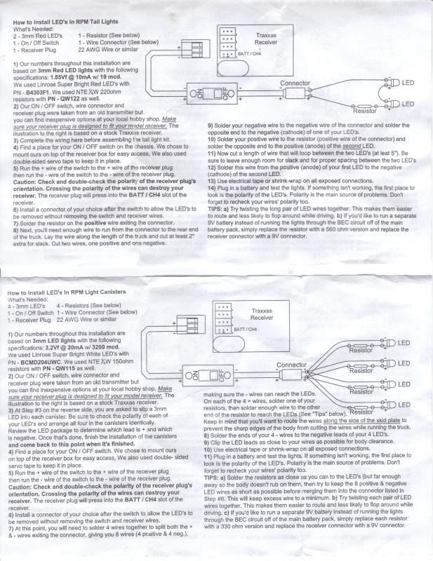
    hey gents... i m looking to wire up 6 led's for my slash... 4 for the front and 2 reds for the rear... going for a desert truck looks... i have downloaded the rpm instructions and it looks pretty clear but i m wondering if some electronic experts here can help me... sorry about the size of the downloads...

    i d like to add 2 more sets of wires (for the rears) to the bottom set of instructions... would it be OK to just run 2 more sets of wires (4 total strands - to power the red RED led's) where the 4 sets of wires exit AFTER the 'connector' ??

    hopefully that makes sense... i don t see any reason why it wouldn t work... maybe i ll need to put in different resistors or lower 'mcd' LED's ??

    i ll be running the lights off the rx... it s a spektrum sr3000... using a dx2.0 tx...

    i m piecing together the stuff i need this week and i d like to get this thing dialled ASAP... hopefully some people with alot more experience with wiring LEDs can help me out

    cheers


  • Diegoboy
    Administrator
    • Mar 2007
    • 7244

    #2
    I didn't read through your post, I'm in a hurry right now, but from what I skimmed through, I think you may find this useful.
    "A quick temper will make a fool of you soon enough."
    . . . . . . . . . . . . . . . . . . . . . . . . . . . . . . . . . . . . .Bruce Lee. . . . . . . . . . . . . . . . . . . . . . . . . . . . . . . . . . . . . . . .

    Comment

    • ozboater
      Senior Member
      • May 2007
      • 415

      #3
      thanks diego, i ll check it out

      Comment

      • ozboater
        Senior Member
        • May 2007
        • 415

        #4
        link is good diego but it doesn t seem to give me the option to link up LED's of differing specs in a series...

        Comment

        • ozboater
          Senior Member
          • May 2007
          • 415

          #5
          c'mon lads, someone must have half a clue (i have 1/16 of an idea of what i m doing here)

          Comment

          • BigBen2k
            Junior Member
            • Feb 2010
            • 7

            #6
            It's somewhat easier than it looks.

            First, you have to know that the voltage drop across an LED is fixed, and that each LED has a current limit (check the specs).

            If you're doing LEDs in series, then you simply add up each LED's voltages, and subtract the total from your battery/supply's max voltage: the result is the voltage that your resistor must drop. (there will always be a resistor at the end of a chain of LEDs)

            The current is determined by the LED with the lowest current maximum (typical LEDs max current is 20 mA). The same current will flow through your resistor.

            Once you know the voltage and current of the resistor, simply use V=R * I to calculate the resistance value (V= voltage, I= current, R= resistance).

            Example:
            3 LED in series.
            Spec of LED: drops 1.4 volt, max 20 mA
            Battery: 7.4 volts max

            voltage of resistor = 7.4 - (3 * 1.4) = 3.2
            current through resistor = 20 mA (0.020 Amps)

            Resistor value = 3.2 / .020 = 160 Ohms.

            *always* pick a resistor that has a slightly higher value, to make sure that you don't exceed the current limit.

            Comment

            • ozboater
              Senior Member
              • May 2007
              • 415

              #7
              bigben2k... thanks, that help me out for sure...

              i m a little confused a to the voltage of the LED's...

              the WHITE one have the specs: 3.2 Vf @ 20mA w 3200mcd


              the RED ones : 1.85 Vf @ 10mA w 19mcd

              so the voltage of the LEDS is 3.2 and 1.85 respectively ???

              no problems then hooking up 4 WHITE LEDS and 2 RED LEDS even tho they are of different brightnesses ??

              sorry for all the questions mate... can you tell that i m a newbie at this stuff :)...

              in the above supplied RPM instructions, they have a resistor for every LED... do i need that or is just one resistor ok ??

              cheers
              Last edited by ozboater; 02-10-2010, 12:15 AM.

              Comment

              • Diegoboy
                Administrator
                • Mar 2007
                • 7244

                #8
                MCD = millicandelas
                The unit of measure commonly used to describe LED intensity is the millicandela (mcd), 1000 millicandela equals 1 candela. Candelas measures how much light is produced as measured at the light source.


                Your white ones are far brighter than your red ones.

                Try getting some red ones that are more compatable to your schematic and brightness.
                If they're 5mm try these
                If they're 3mm try these
                "A quick temper will make a fool of you soon enough."
                . . . . . . . . . . . . . . . . . . . . . . . . . . . . . . . . . . . . .Bruce Lee. . . . . . . . . . . . . . . . . . . . . . . . . . . . . . . . . . . . . . . .

                Comment

                • ozboater
                  Senior Member
                  • May 2007
                  • 415

                  #9
                  i guess that they spec the lower mcd for the RED LEDs since they are for the rear tail light and are therefore meant to be dimmer ??? sounds reasonable...

                  the truck will be using 3mm LEDs all round.. thats what the canisters hold..

                  is it not recommended to wire up LEDs that differ greatly in the 'mcd' rating... i mean the whites are 3200 mcd and the reds are 19 mcd... is this too much of a difference ??

                  cheers again lads, i appreciate the help... i ll get this bastid sooner or later (with some help of course)

                  Comment

                  • Diegoboy
                    Administrator
                    • Mar 2007
                    • 7244

                    #10
                    You can wire them up no problem. I, myself, would like brighter red ones.

                    Here's your schematic.
                    Attached Files
                    Last edited by Diegoboy; 02-10-2010, 02:00 AM.
                    "A quick temper will make a fool of you soon enough."
                    . . . . . . . . . . . . . . . . . . . . . . . . . . . . . . . . . . . . .Bruce Lee. . . . . . . . . . . . . . . . . . . . . . . . . . . . . . . . . . . . . . . .

                    Comment

                    • ozboater
                      Senior Member
                      • May 2007
                      • 415

                      #11
                      sweet diego... cheers

                      so there is no worries running this off of my spektrum rx ??? what voltage typically does a rx provide ??

                      i can make good sense of the diag... but does anything differ since i m only using 2 red LEDs ???

                      you guys have been a great help...

                      thank again

                      oz

                      Comment

                      • Diegoboy
                        Administrator
                        • Mar 2007
                        • 7244

                        #12
                        This is being powered from the RX? Hold on, that changes things...
                        "A quick temper will make a fool of you soon enough."
                        . . . . . . . . . . . . . . . . . . . . . . . . . . . . . . . . . . . . .Bruce Lee. . . . . . . . . . . . . . . . . . . . . . . . . . . . . . . . . . . . . . . .

                        Comment

                        • Diegoboy
                          Administrator
                          • Mar 2007
                          • 7244

                          #13
                          Ok... I fixed it
                          "A quick temper will make a fool of you soon enough."
                          . . . . . . . . . . . . . . . . . . . . . . . . . . . . . . . . . . . . .Bruce Lee. . . . . . . . . . . . . . . . . . . . . . . . . . . . . . . . . . . . . . . .

                          Comment

                          • ozboater
                            Senior Member
                            • May 2007
                            • 415

                            #14
                            dude, thats awesome... now i can get it going... i ve been procrastinating with this damn project since i didn t really know how to wire it up...

                            so that schematic is golden assuming 4 X 3200 mcd WHITE LEDs and 2 X 19 mcd RED LEDs ??? if i read above correctly then it really doesn t matter about the mcd rating... just that a different mcd rating will change the resistors i use... sound correct ??

                            do ya reckon it ll effect my run time significantly ?? i plan on putting in a simple switch so i can turn them off for daytime running... ought to be a sweet project, i ll post photos when shes done !!

                            Comment

                            • Diegoboy
                              Administrator
                              • Mar 2007
                              • 7244

                              #15
                              The MCD has no direct affect on the resistor, it's the fwd voltage and the current, but the mcd does affect the current, therefore affecting the resistor indirectly.
                              LED's draw such little current, you will never notice any runtime difference.
                              "A quick temper will make a fool of you soon enough."
                              . . . . . . . . . . . . . . . . . . . . . . . . . . . . . . . . . . . . .Bruce Lee. . . . . . . . . . . . . . . . . . . . . . . . . . . . . . . . . . . . . . . .

                              Comment

                              Working...