Darin's Race Prep - Pro Boat Impulse 31 V2

Collapse
X
 
  • Time
  • Show
Clear All
new posts
  • Darin Jordan
    Fast Electric Addict!
    • Apr 2007
    • 8335

    #1

    Darin's Race Prep - Pro Boat Impulse 31 V2

    It's been awhile since I've done a race prep thread, and I decided to see if I could apply the things I've learned over the past couple of years racing these IM31's to a new V2 version.

    I'm starting with a fresh hull, which Pro Boat provided me just after these came onto the market. I think this one one used as a paint sample, and has metallic black paint, instead of just black, so I believe it's somewhat "one of a kind"...

    I stripped out the hull, removing all the hardware and velcro, etc... As some have mentioned on their boats, one of the servo mounting blocks had come lose. Otherwise, everything looked fine. A quick inspection of the hull revealed no cracks or other damage, so it's clean place to start.

    My first task was to true the bottom. It's something that needs to be done on ANY composite hull you are going to race, so might as well get it out of the way first.

    Took some block sanding, then a LITTLE bit of filling, and then a little more sanding. Hull wasn't too bad. I know they vary, so just be persistent and take your time. It's important to get this flat and also to make the trailing edges as close to 90-degrees as you can.

    I also re-epoxied the servo mounting block back in place. Not fond of this servo mounting setup (or the wood interior in general), but we'll work with what's here. Not worth the time to replace it. Once the servo is in place, I've rarely had to change one...
    Attached Files
    Last edited by Darin Jordan; 09-16-2013, 11:26 AM.
    Darin E. Jordan - Renton, WA
    "Self-proclaimed skill-less leader in the hobby."
  • Darin Jordan
    Fast Electric Addict!
    • Apr 2007
    • 8335

    #2
    The first "improvement" I wanted to make was to remove a little weight, and also to see if I could get the CG lower.

    To accomplish this, I decided to remove the center of the battery tray. Since this hull will be used with a single 4S 5000mAh style pack, this will allow me to position the cell deep in the V, lowering the CG considerably. Hopefully that will make the hull more balanced and help to keep it upright.

    To remove the tray, I used a carpet knife and took my time to cut down through the tabs interlocking the tray into the side rails. I am leaving the side-rails in place to retain the rigidity.

    After cutting down all the way through the side tabs, I used a small saw to trim the aft tabs off.

    To get the foward part out required some "muscle"... I got the rest of the trail loose, then went up and down with it and eventually it worked out of the front crossmember up under the deck.

    Once the tray was removed, I carefully trimmed and knocked out the remaining tab pieces from the side-rails. I may use these to mount velcro straps to act as battery hold-downs later on.

    Overall, it looks like the tray and hold-down assembly removal took almost 4oz out of the weight of the boat. That's pretty significant.
    Attached Files
    Darin E. Jordan - Renton, WA
    "Self-proclaimed skill-less leader in the hobby."

    Comment

    • Darin Jordan
      Fast Electric Addict!
      • Apr 2007
      • 8335

      #3
      Once I was finished removing the battery tray and cleaning up the interior, I did my typical epoxy coating of all the interior wood parts. I don't do anything fancy... just mix some medium cure epoxy up and apply it to all of the wood using an acid brush. I put on a thin coat, and extend it one-brush-width onto the glass of the hull itself. I also coated the glass in around the motor area and back by the driveshaft. I think this helps reduce the grease staining that seems to take place in this area from the "fling-off" that occurs... Just makes for an easier clean-up and a nicer presentation.

      Once the epoxy dried, I mixed up 20cc's of 2lb density Two-Part Expanding foam and poured it down the left side of the inside of the hull, trying to target from about the front bulkhead forward. I tilted the hull to run the still liquid mixture up the sides of the front of the hull toward the tip, trying to evenly distribute it.

      Once the left had expanded, I repeated on the right.

      Finally, I mided up about 15cc more and VERY carefully applied it down the center area of the underside of the deck. I didn't want to FILL this area, as I've had very bad experiences with this foam when traveling to LA with it sucking down the deck in the heat. I was able to use a straight edge to break it loose from the deck and restore the deckline, but I'm hoping not to have to repeat that again. I just ran this application down the center of the deck, toward the tip, and let it expand. This makes the deck more rigid and prevents hatch blow-offs under a hard hit that would have otherwise compressed the deck.

      One NOTE: As the foam was expanding (happens in a matter of seconds once it kicks off), I used a blue-ice back on the outside of the hull to keep the glass cool while the foam was kicking off. I'm hoping this helps retains the hulls integrity a bit. It gets pretty hot otherwise.

      The overall effect of this update is that the front of the boat is MUCH less likely to sustain damage or split open upon impact. It's pretty solid down the sides and the deck doesn't compress. Also now has the required floatation. Basically, I'm using the added floatation as struture which otherwise wouldn't be provided by your typical pool noodle...

      After the epoxy and the foam installation, the weight ticked back up a bit, but since this prep would have been done anyhow, the overall net is still about 4oz down.
      Attached Files
      Darin E. Jordan - Renton, WA
      "Self-proclaimed skill-less leader in the hobby."

      Comment

      • Darin Jordan
        Fast Electric Addict!
        • Apr 2007
        • 8335

        #4
        As everyone knows, the hatches in these are a little thin (Something that will be corrected at some point with these), so I wanted to apply a layer of Carbon Fiber to prevent damaging the hatch. Adds a little weight up high, but this part needs to be solid for racing survival.

        I cut a piece of 5.5oz Carbon Weave to roughly fit, leaving about an inch all the way around. I then sprayed a LIGHT coat of Scotch Super 77 Spray Adhesive onto the cloth, and carefully stuck it down into place. I trimmed off the excess with some sharp scissors, mixed up some epoxy, and wetted out the cloth, taking care not to get it overly wetted. I cured this overnight.

        Once cured, I used a block sander to sand down the rough edges and clean up the edge.
        Attached Files
        Darin E. Jordan - Renton, WA
        "Self-proclaimed skill-less leader in the hobby."

        Comment

        • Darin Jordan
          Fast Electric Addict!
          • Apr 2007
          • 8335

          #5
          In the past, I've found that my Monos seems to handle better using a tapered rudder as opposed to a straight rudder. I tested this theory at the 2012 Nats with my P-Ltd Mono version of the IM31 V1 by modifying an original Miss Geico to fit it to the IM31 mounting. It worked well, and I finished 3rd overall at the event, behind two race-purpose-build DF26 Monos...

          I'm going to do that here as well. I'm starting with a new MG29 rudder. The modification is pretty simple, really. You just need to remove some material and drill a couple of holes.

          The MG29 rudder is also a bit thinner at the trailing edge, which should help reduce drag. The taper, reduced drag, and the ability to adjust tilt, ought to make for a wide range of tuning adjustment.

          First step is to remove some material, which I will do using my Mill, but which could easily be done using a simple hacksaw or bandsaw...
          Attached Files
          Darin E. Jordan - Renton, WA
          "Self-proclaimed skill-less leader in the hobby."

          Comment

          • Darin Jordan
            Fast Electric Addict!
            • Apr 2007
            • 8335

            #6
            To complete the mods to the rudder, I marked out the area that needed to be removed by laying the factory rudder on top.

            Used a band-saw to trim the section out, sanded it, and then drilled out the holes to match. If you cut it just right, and JUST cut it back to the back of the first mounting hole for the orginal steering arm, the second hole lines up perfectly with the IM31 rudder bracket.

            I drilled out the lower hole and it all bolted together perfectly.

            New blade is tapered, and thinner than the stock IM31 blade. Still fully adjustable as well.

            To top it off, I rounded the bottom of the blade to kill any lift in that area, and then used JB-weld to reseal the bottom hole.
            Attached Files
            Darin E. Jordan - Renton, WA
            "Self-proclaimed skill-less leader in the hobby."

            Comment

            • Darin Jordan
              Fast Electric Addict!
              • Apr 2007
              • 8335

              #7
              Got the bottom finished up and put on a coat of primer, then a few coats of flat white enamal.

              Now that that is dry, I can start assembling the hull again.

              For the trim tabs, I've never really seen the need to use aftermarket on these boats, though I did design the mounting to be a direct bolt-on replacement for the Speedmaster 1.5" tabs. :)

              After talking with Greg Schweers about tabs a bit ago, I decide to see if the boat would settle into the turns a little better if I used shorter trim-tabs. They are 1.5" stock. I trimmed these down to 1".

              Also, I'm going to be using a set of OSE IM31 replacement turn-fins. I designed these and have tested them extensively. They turn the IM31 into a whole new boat when it comes to turning in race water.

              When mounting the fins, it's important that they are parallel to the keel, and that the bottoms are mounted parallel to the bottom of the boat as well. I used a 1-2-3 block against the transom to get the mounting brackets correctly aligned, and then a long straight edge along the bottom of the fin itself to make sure that was correctly aligned. Once there, simply bolt everything down snug.
              Attached Files
              Darin E. Jordan - Renton, WA
              "Self-proclaimed skill-less leader in the hobby."

              Comment

              • Darin Jordan
                Fast Electric Addict!
                • Apr 2007
                • 8335

                #8
                After mounting the tabs and the turn fins, I prepped the stuffing tube for the remounting of the strut.

                The factory "grease" in these things is STICKY! Way too much so.

                I took a pipe cleaner and bent it in half, then twisted it together, and put some solvent on it. Chucking it up in my drill, I ran it up and down inside the stuffing tube until it was cleaned up. You wouldn't believe how much smoother the flexshaft turned!

                I use either Pro Boat grease, or a special mixture, neither of which cause that much drag.

                The "teflon" (not convinced that's what it really is!) extended a bit too far into the strut, so I used a 3/16" reamer and trimmed away a bit of the aft end of it. I also ran the reamer through the bushing to help debur it.

                You have to inspect the flex cable and bushing fit very carefully. Sometimes they are great, other times they are sloppy, or the cable isn't straight in the stub-shaft, etc. Use your best judgement to figure out where to go from here. OSE makes some FANTASTIC upgrads in this area. Take advantage if you need to.

                My flex and the fit in the bushing was OK for now, and the flex was straight, so I'm just going to run the factory stuff. Haven't had one fail yet, and I've ABUSED them, so it should hold up fine. Biggest drawback to the factory flex cable is that the propshaft is a tad on the short side aft of the drive-dog, so longer hubbed props are more difficult or impossible to fit. Shouldn't be a problem with my intended application, which will likely be limited to P-Ltd action.
                Darin E. Jordan - Renton, WA
                "Self-proclaimed skill-less leader in the hobby."

                Comment

                • Darin Jordan
                  Fast Electric Addict!
                  • Apr 2007
                  • 8335

                  #9
                  With a mock-up motor in place, fitted the driveshaft.

                  Mounted a new Spektrum S6020 Digital Servo, which are awesome pieces. Metal gears, 140+oz/in, etc.. Very precise and I have had really good luck with their performance.

                  Before remounting the servo, I went ahead and ran a small drillbit down the holes to ensure they were deep enough and wouldn't cause the screws to pull the laminations apart.

                  Mounted the servo, and connected up the stock steering arm. It's a little bit of a smallish steering rod, but it's designed to PULL the rudder into right-hand turns, and I haven't had any issues with precision with these boats, so I'll keep using the stock one until it doesn't server me well any longer. The less prep work I have to do, the better! :)

                  Added Velcro in the appropriate areas, installed the RX, and also replaced the rubber antenna bushing with a nicer Pro Boat antenna mount. These are the ones from the old Miss Elams, etc. I think they still offer them at Horizon.

                  To install the antenna mount, open the hold up to 7/32", (drill right through the rubber bushing... it'll pop right out) and then remove a ring of the paint around the hold to expose some bondable surface. Also rough up the base of the mount.

                  Swirl a bit of good epoxy under the base, press it in place, and tape down for the night to dry.
                  Attached Files
                  Darin E. Jordan - Renton, WA
                  "Self-proclaimed skill-less leader in the hobby."

                  Comment

                  • Darin Jordan
                    Fast Electric Addict!
                    • Apr 2007
                    • 8335

                    #10
                    I'm about at a stopping point for now. Have to figure out what power system I'll run. After the epoxy dries on the antenna mount, I'll do the final prep to get it fully ready to install a power system, and then we'll figure out which way to go.
                    Attached Files
                    Darin E. Jordan - Renton, WA
                    "Self-proclaimed skill-less leader in the hobby."

                    Comment

                    • Darin Jordan
                      Fast Electric Addict!
                      • Apr 2007
                      • 8335

                      #11
                      Forgot to mention...

                      I adjusted the strut height to approximately .250" up from the keel.

                      The flooded stuffing shafts on these allow the strut to move up quite a bit, but the damn brass they use is WAY too thick and rigid. Getting the strut much lower is really difficult, depending on the boat you have. Some are easier than others. However, thus far, this is a good prop height for the size of props you'll want to run. Keeps the keel in contact with the water at speed, etc.
                      Attached Files
                      Darin E. Jordan - Renton, WA
                      "Self-proclaimed skill-less leader in the hobby."

                      Comment

                      • TheShaughnessy
                        Fast Electric Addict!
                        • Mar 2011
                        • 1431

                        #12
                        i noticed you have your water cooler all the way towards the rear of the motor. Do you feel like it gives more use full cooling in that area. Im running a 1800 kv in my MG ( i know its a revolt thread) swinging a fairly large prop, not having any heat issues but figure the cooler the better.

                        Comment

                        • lenny
                          Fast Electric Addict!
                          • Sep 2010
                          • 4293

                          #13
                          The cooler is also upside down in the pictures,
                          TheShaughnessy do you have any pictures of your setup in the hull ?
                          ? ONLY IF THEY WORK

                          My youtube videos.http://www.youtube.com/user/61manx?feature=mhee

                          Comment

                          • Darin Jordan
                            Fast Electric Addict!
                            • Apr 2007
                            • 8335

                            #14
                            Motor is just a mockup, guys, so I could fit the motor mount, etc..
                            Darin E. Jordan - Renton, WA
                            "Self-proclaimed skill-less leader in the hobby."

                            Comment

                            • Darin Jordan
                              Fast Electric Addict!
                              • Apr 2007
                              • 8335

                              #15
                              Received some parts from Horizon Hobby this week, so the Prep continues.

                              As you've already read, I'm doing a little R&D and experimenting with this boat, so why stop with the setup?? I'm going to try something different in the ESC department as well.

                              The stock 80A ESC is bullet-proof... It'll push a lot of amps through it without missing a beat. It's water-proof, comes with large 12-awg wire on it, and just plain works.

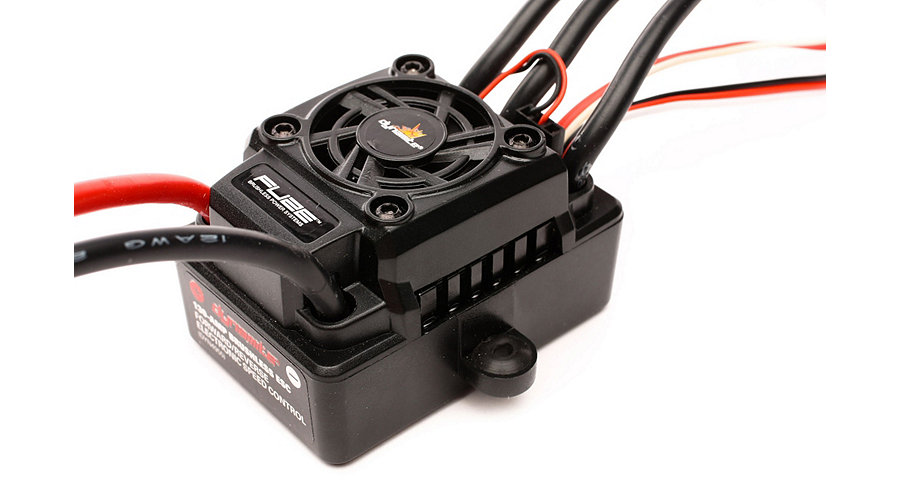
                              For this boat, however, I wanted to see if I could try something different. I'm going to use the Fuze 130A Sensorless BL Waterproof ESC: 4WD SCT 1/8 by Dynamite (DYN4955).


                              This ESC is waterproof, has large 12-awg wire, is programable, and comes with a nice enclosed cooling-fan setup.

                              I have run the Fuze products in my RC Trucks and they seem to hold up very well. Throttle is very smooth, they are programable for certain features, etc..

                              We'll try it out here in the Impulse V2 and see how it holds up.

                              I'm NOT going to add water-cooling at this time. Experience shows that the P-Ltd power systems don't typically draw more than 75-85 Amps on average, and this ESC is publically rated at 130A, which is likely conservative. I'll monitor temps on this and see if the water cooling is actually necessary for a P-Ltd ESC. If not, that's just more cooling capacity for the motor, which is where it's really needed.

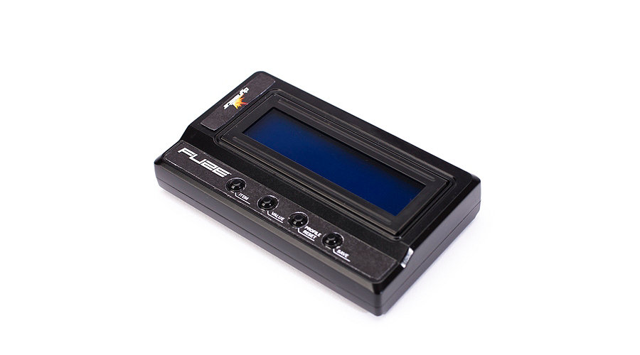
                              This ESC can be programmed with a separate programming box.

                              FUZE ESC Digital Program Box: DYN4850, DYN4955 by Dynamite (DYN3748)


                              It's $60.00... After I use it a few times, I'll let you know if it's something that is "needed"... I believe the ESC can be programmed with the TX as well.


                              So, what do I expect?? I expect that the this ESC setup will perform very well. I think the throttle response will be exceptional and very smooth, allowing for better control off the corners, especially in an Offshore situation. I think it will hold up very well, will not require water cooling, and overall, will be a good option.

                              One way to find out...
                              Attached Files
                              Darin E. Jordan - Renton, WA
                              "Self-proclaimed skill-less leader in the hobby."

                              Comment

                              Working...