Page 1 of 15 12311 ... LastLast
Results 1 to 30 of 478

Thread: BBY Micro Turbine Hydro for SSSH

Hybrid View

Previous Post Previous Post   Next Post Next Post
  1. #1
    Join Date
    Sep 2007
    Location
    CA
    Posts
    1,707

    Cool BBY Micro Turbine Hydro for SSSH

    As the founding member of the Santee Lakes Old Boater’s Society (the SLOBS), and “President for Life” (a.k.a. der Führer), I am always trying to promote our unique brand of FE racing. The boating area at Santee lakes is limited by several steel-reinforced concrete bridge piers and a three-ton rock in the middle of the pond. LSH boats can run in our pond, but they spend a lot of time turning real tight corners. Super-fast N-2 boats run out of room REAL fast at our pond. P-sized and larger hulls are out of the question. The bridge and rock do not move when hit by boats. I know this for a fact from watching other people try.

    Our motto at Santee Lakes is “Fast, Cheap, and Out of Control”, but how can you do FAST in such a small area? As many of you may know from the “Red” forum, I have been focusing on a spec class called Santee Sport Scale Hydro or SSSH for short. I have decided to post a build thread on this forum to expose more people to the concept of CHEAP racing.

    SSSH, like LSH, specifies a particular hull, motor, and battery combination. SSSH hulls have a 400 mm (15.7”) maximum length and must resemble a “real” hull (no outriggers). Plastic propellers (cheap) are required, and can be modified if desired. The SSSH “Spec” motor is a cheap 3000 rpm/V brushless outrunner that can be purchased on ebay for under $26 delivered, and that price includes a 30A ESC. It doesn’t get much cheaper than that. For batteries, 2S LiPo, or 6 round cells of 1000 to 1950 mah are the accepted cells. I have seen 1500 mah 2S packs at UH for around $10 to $12. This motor/prop combo draws about 10 to 12 amps so runtimes will be 6 to 12 minutes, depending on your setup and the current draw will be well below 15C for just about any setup. You don’t need high-discharge cells to race SSSH. This motor/battery combo has enough power to blow these little hulls off the water if your set-up is not right, so I would say that they qualify as “Fast” enough. SSSH racing specifies 4-minute heats on a 2-buoy course, sized to your particular pond.

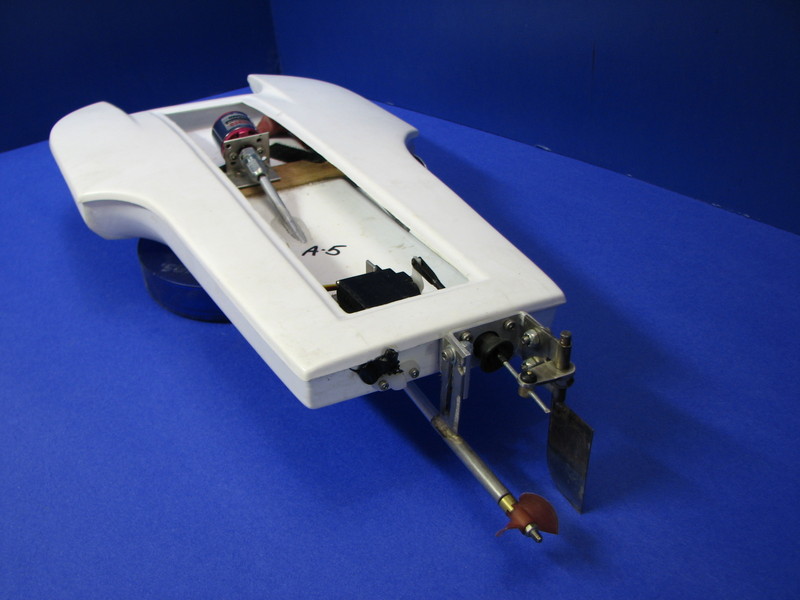
    This build will be a Micro Turbine Hydro (MTH) from Blew By You Racing. At $30 for the hull, this kit fits perfectly into the philosophy of “Cheap” racing. I should be able to have this boat ready to race with receiver, servo, and battery for under $200. Using parts and radio bits I have lying around the shop, it is possible to cut that dollar figure nearly in half. I plan to laser-cut the internal wood frame, similar to the wood frame in the Campbell Classic Hydro kit. This is “prototype” work; therefore, I will not include the laser-cutting costs in my total, since this could be just as easily done by hand with a saw and some sandpaper. I’m going to do it that way because I’m lazy and I may have need for additional wood bits in the future. If it works out, I may make the CAD files available to Randy at BBY for his use.

    For this build, I will be using a 2 mm stainless steel driveshaft (no flex or wire drive), a 2.3 mm x 2.0 mm motor coupler, a micro brass rudder, and Graupner K29 propellers from MHZ. These props are cheap, ready-to-run, and require no balancing/sharpening. While the rudder is not super-cheap, it is cheap enough when compared to Fuller, Solinger, Speedmaster, and similar CNC-cut aluminum rudder assemblies. Furthermore, ordering all your bits and pieces from one supplier reduces shipping costs by spreading them around several parts. The flanged 2 mm x 5 mm ball bearings are available from Boca Bearings at a nominal cost. The stuffing tube is a carbon fiber tube that I got from a kite supply store (I have a lot of these in my shop). The I.D. of these tubes is a bit less than 5 mm, but some careful sandpaper work should easily re-size the I.D. to fit the bearings. In order to “keep it simple” and cost-effective, I will limit the use of carbon fiber to just the stuffing tube, and possibly the turn fin. All other materials will be of “conventional” construction to make it easy for everybody to duplicate this build if desired.

    I’ll post some photos of the current parts inventory later tonight when I get home.
    Last edited by Dr. Jet; 06-09-2008 at 03:08 PM.

  2. #2
    Join Date
    Apr 2007
    Location
    On
    Posts
    7,279

    Default

    "SLOBS",,,,, I love it !

  3. #3
    Join Date
    Sep 2007
    Location
    CA
    Posts
    1,707

    Default

    We were going to name ourselves the Santee Lakes Unlimited Thunderboat Society, but somehow that just didn't work out.

  4. #4
    Join Date
    Apr 2007
    Location
    On
    Posts
    7,279

    Default

    You made the better choice!

  5. #5
    Join Date
    Apr 2008
    Location
    MN
    Posts
    197

    Default

    I have been eyeing your other thread on this subject. I think this is great. This size boat fits a nitch that needs more attention. New technology has realy given this area a leg up and organizing it into a class as you have can make it stick.

  6. #6
    Join Date
    Apr 2007
    Location
    Nj
    Posts
    4,735

    Default

    I am all about this type of boat. I really look foward to this one!!!

  7. #7
    Join Date
    Apr 2007
    Location
    Wa
    Posts
    5,905

    Default

    Wish I lived closer to the SLOBS

    Jim
    "Our society strives to avoid any possibility of offending anyone except God.
    Billy Graham

  8. #8
    Join Date
    Sep 2007
    Location
    CA
    Posts
    1,707

    Default

    OK, here are some photos of my inventory. You can see I am making a paper template for the forward bulkhead. I will scan it and bring it into AutoCAD as a photo image. Then I trace it in AutoCAD, print some copies, cut them out to test-fit in the hull. When everything fits, I do the same with the transom and the stringers. Then to the laser-cutter guy for a bunch of pre-cut plywood parts.

    The photos show the MHZ shaft and rudder, the bearings and if you look, the CF tubes. The little bit of aluminum angle is for the turn fin mount.

    Here is an interesting thought. I have some of Joe's hardware on my Campbell Classic. His equipment is some of the nicest work out there. How about a micro strut and rudder Joe?
    Attached Images Attached Images

  9. #9
    Join Date
    Sep 2007
    Location
    CA
    Posts
    1,707

    Default Part Numbers and Prices

    Here are the part numbers and prices of the bits I will be using:


    MHZ:
    Rudder Assembly, part m-1742/8 $24.50
    2mm SS Prop Shaft, part g-3276 $ 2.90
    Brass Prop Bushing, part g-3272 $ 5.00
    Motor Coupler, part g-3279 $ 8.70
    K29 Propeller, part m-2318/29R $ 5.50

    Boca Bearings:
    2mm x 5mm Flanged SS Bearings, part SMF52 (2 ea. Req’d) $10.80

    Ebay:
    Motor and ESC $25.98

    It looks like $94.18 (plus S&H) will get you everything you need. Motor, controller, hardware, driveline, and propeller. CHEAP!

  10. #10
    Join Date
    Sep 2007
    Location
    CA
    Posts
    1,707

    Default Motor and ESC

    Here's a link to the SSSH motor/ESC combo. This auction ends soon, but just go to his ebay store, you will find more of these there.

    http://cgi.ebay.com/3000-Helicopter-...QQcmdZViewItem

    Less than $26 for a motor AND an ESC? What a deal!

  11. #11
    Join Date
    Sep 2007
    Location
    CA
    Posts
    1,707

    Default Transport and Storage

    One of the many advantages to SSSH racing is the ease of transport and/or storage of your fleet. I can fit 7 boats, a rescue boat, all my tools, batteries, chargers, fishing poles, food, and drinks, in the trunk of a ’92 Toyota Celica and still have room for a few more boats.

    The attached photos were taken when my “Blast-O-5000” camera was having “issues” so the shots are a little fuzzy, but they still convey the point.
    Attached Images Attached Images
    Last edited by Dr. Jet; 06-10-2008 at 03:57 PM.

  12. #12
    Join Date
    Apr 2008
    Location
    MN
    Posts
    197

    Default

    Quote Originally Posted by Dr. Jet View Post
    OK, here are some photos of my inventory. You can see I am making a paper template for the forward bulkhead. I will scan it and bring it into AutoCAD as a photo image. Then I trace it in AutoCAD, print some copies, cut them out to test-fit in the hull. When everything fits, I do the same with the transom and the stringers. Then to the laser-cutter guy for a bunch of pre-cut plywood parts.

    The photos show the MHZ shaft and rudder, the bearings and if you look, the CF tubes. The little bit of aluminum angle is for the turn fin mount.

    Here is an interesting thought. I have some of Joe's hardware on my Campbell Classic. His equipment is some of the nicest work out there. How about a micro strut and rudder Joe?
    It's something that has been on and off the table for a couple years. Maybe now is the time. Hardware does seem to be the sticking point with micros.

  13. #13
    Join Date
    May 2008
    Location
    WA
    Posts
    44

    Default

    Hi Dr. Jet!

    I thought this was the forum your were talking about. Thanks for the link! I really like your concept. I have two boys who I would love to get involved with this, and at these prices I think it's really feasible. I will keep watching this thread to see what you do with them.

    Thanks,
    Mike

  14. #14
    Join Date
    Jun 2007
    Location
    BC
    Posts
    5,190

    Default

    Dr. Jet

    You are the man and I believe I have the stature of honourary member from 3 months ago.

    Cheers

    Douggie

  15. #15
    Join Date
    Apr 2008
    Location
    MN
    Posts
    197

    Default

    What is the transom width and height on the bby hydro? I will do some chewing on it.

  16. #16
    Join Date
    Sep 2007
    Location
    CA
    Posts
    1,707

    Default Transom dimensions

    Allowing for some trimming, 1/2" high x 4-1/8" wide.

  17. #17
    Join Date
    Sep 2007
    Location
    CA
    Posts
    1,707

    Default Motor and ESC

    Here's the "Spec" motor and controller.
    Attached Images Attached Images

  18. #18
    Join Date
    Sep 2007
    Location
    CA
    Posts
    1,707

    Default

    My first group of photos showed the MHZ 2mm stainless steel propshaft. This particular shaft has been shortened to fit the Geckos. I do not recall exactly how much I cut off to make them fit. I just ordered more propshafts from MHZ, and my plan is to size everything and locate the motor according to the full length of the stock shaft with no trimming. The idea here is that the longer the shaft is; the flatter the propshaft angle will be. When the propshafts arrive, I’ll cut a stuffing tube to length, and have my driveline ready to install. Cheap and simple! For those planning a similar build, not cutting the propshafts is one less step in building your SSSH racer.

    I already have the motor and coupler drawn in AutoCAD; so once I have the exact length measurement of the shaft, I can finalize the motor location and shaft angle. Once I have that, I can start designing the plywood parts.

    Stay tuned for more.

  19. #19
    Join Date
    Sep 2007
    Location
    CA
    Posts
    1,707

    Default Designing the Internal Framework

    I will be starting on my preliminary CAD drawings for the wood parts when I get home tonight. At this point, without the driveshaft, I will focus on the forward bulkhead, the stringers, and the transom. My ultimate goal is to tie all the various structural members together to eliminate stress risers or flex points, and create a light, yet stiff structure.

    To this end, the motor mount will be tied to the forward bulkhead and the stuffing tube, and this entire assembly will be tied to the transom. This should eliminate hull flex where the stuffing tube passes through it, and maintain motor/prop shaft alignment. The motor mounting holes will be “slots” to allow easy motor installation and removal in a somewhat cramped area. The transom and forward bulkhead will be tied to the stringers, which should yield a very stiff structure without a lot of weight. The framework alone will have very little resistance to tensional loads; however, when “skinned” with the hull which will act as a shear member, the resulting structure should be extremely stiff, especially considering the small size. Remember that the bending moment of a piece is essentially a function of the cube of the aspect ratio of the part, and the smaller the part, the stiffer it is. This same stiff structure result has been achieved in the Campbell Classic, and now in the Vac-U-Pickle. The plywood parts for the MTH will have a “lattice” appearance to reduce weight while maintaining the shear resistance of the individual plywood parts. For test-fitting, I will run a print of the drawings, and paste them on some scrap balsa I have in my shop. Then, I will rough-cut the parts from the aforementioned balsa sheet (without the lattice work, of course) with an X-Acto knife and test-fit them in the hull to confirm that everything fits according to plan.

    When everything fits, it will be time to start talking to the laser-guy.

  20. #20
    Join Date
    Sep 2007
    Location
    Co
    Posts
    3,915

    Default

    Quote Originally Posted by J Solinger View Post
    What is the transom width and height on the bby hydro? I will do some chewing on it.
    The way I build mine I measured 7/8 of a inch for the transom and my bracket is 3/4 of a inch. It would be nice to have a machined bracket, I will be watching to see what you do.

    Randy
    For ABS, Fiberglass, Carbon hulls and Stainless hardware
    BBY Racing

  21. #21
    Join Date
    Sep 2007
    Location
    CA
    Posts
    1,707

    Default

    Randy,

    My preliminary plans are to have the front edge of the prop hub (where a drive dog would normally be) ½” behind the transom and ½” below the bottom of the hull (even with the sponson bottoms). As you can see from the sketch, I will have about 6-1/4º of “down” angle at the prop. The Graupner props are very similar to an Octura “X” series with some tongue removed, so I gather they are low-lifting like the Octuras
    Last edited by Dr. Jet; 06-12-2008 at 01:41 PM.

  22. #22
    Join Date
    Apr 2007
    Location
    Wa
    Posts
    5,905

    Default

    Being the scale geek that I am having the prop so far back of the transom just looks very wired to me. Does it really need to be back so far?
    Jim

    Quote Originally Posted by RandyatBBY View Post
    The way I build mine I measured 7/8 of a inch for the transom and my bracket is 3/4 of a inch. It would be nice to have a machined bracket, I will be watching to see what you do.

    "Our society strives to avoid any possibility of offending anyone except God.
    Billy Graham

  23. #23
    Join Date
    Apr 2007
    Location
    Au
    Posts
    446

    Default

    Quote Originally Posted by JimClark View Post
    Being the scale geek that I am having the prop so far back of the transom just looks very wired to me. Does it really need to be back so far?
    Jim
    I'm with Jim, I don't mean to be critical but why on earth is the prop so far behind the transom ?
    This 'stinger' type strut is only used on DV hulls to get the prop in clear water, hydros work fine with the prop close to the transom.
    Graham.

  24. #24
    Join Date
    Sep 2007
    Location
    CA
    Posts
    1,707

    Default

    I'm with Jim on this too. I plan to have the prop about 1/2" from the transom.

  25. #25
    Join Date
    Apr 2007
    Location
    WA
    Posts
    8,335

    Default

    Seems like a perfect application for a .047" Wire Drive...
    Darin E. Jordan - Renton, WA
    "Self-proclaimed skill-less leader in the hobby."

  26. #26
    Join Date
    Sep 2007
    Location
    CA
    Posts
    1,707

    Default Wire Drives

    I have successfully used 0.030" wire drives in my other SSSH models. I wanted to do this one with a straight shaft to keep it simple and cheap.

  27. #27
    Join Date
    Sep 2007
    Location
    CA
    Posts
    1,707

    Default MHZ Rudder

    Here is an interesting tidbit. I just received an email from MHZ telling me the rudder assembly I have is no longer available. I sent a response with the part number I have, just to confirm. I’ll let everybody know what the response is.

    Joe,

    If you are reading this, then the need for a decent micro rudder has moved up the priority scale, and you may be just the person to “do it up right.”

  28. #28
    Join Date
    Sep 2007
    Location
    CA
    Posts
    1,707

    Default Fast Response from MHZ

    I just received a response from MHZ to the email I sent out a couple of hours ago. This email said the rudders are temporarily out of stock and should be back in stock very soon.

    Still, I think Joe could come up with something way cool.

  29. #29
    Join Date
    Apr 2008
    Location
    MN
    Posts
    197

    Default

    I am curious to see how the straight drive shaft works out. I have been designing around a wire drive but a straight shaft would simplify things a bunch, and reduce costs.

  30. #30
    Join Date
    Sep 2007
    Location
    CA
    Posts
    1,707

    Default

    Quote Originally Posted by J Solinger View Post
    I am curious to see how the straight drive shaft works out. I have been designing around a wire drive but a straight shaft would simplify things a bunch, and reduce costs.
    Bullseye Joe, that's the whole idea!

Page 1 of 15 12311 ... LastLast

Bookmarks

Bookmarks

Posting Permissions

  • You may not post new threads
  • You may not post replies
  • You may not post attachments
  • You may not edit your posts
  •