Here is a preliminary sketch of the forward bulkhead based on the published dimensions of the MHZ propshaft. I'm thinking of running a "spine" down the centerline of the stuffing tube to keep it from flexing.

 Fast Electric Addict!
Here is a preliminary sketch of the forward bulkhead based on the published dimensions of the MHZ propshaft. I'm thinking of running a "spine" down the centerline of the stuffing tube to keep it from flexing.
Fast Electric Addict!
I have been doing some research on the seller’s store for the “Spec” motor supplier. He has some 9-gram servos in a six-pack for about $5 each. I may add a servo mount in that spine I am planning and size it for these servos. That way, if you get the motor from them, you can order a servo and possibly save on shipping costs.
I have more ideas on this topic that I will reveal when the time is right.
Fast Electric Addict!
That is one thing I hate to do sell one project to fund another. That is a last resort to me. The BBY hull is real cheap.Originally Posted by smm_cbf

Fast Electric Addict!
The way I build mine I measured 7/8 of a inch for the transom and my bracket is 3/4 of a inch. It would be nice to have a machined bracket, I will be watching to see what you do.
Fast Electric Addict!
Randy,
My preliminary plans are to have the front edge of the prop hub (where a drive dog would normally be) ½” behind the transom and ½” below the bottom of the hull (even with the sponson bottoms). As you can see from the sketch, I will have about 6-1/4º of “down” angle at the prop. The Graupner props are very similar to an Octura “X” series with some tongue removed, so I gather they are low-lifting like the Octuras
Last edited by Dr. Jet; 06-12-2008 at 01:41 PM.
Fast Electric Addict!
Seems like a perfect application for a .047" Wire Drive...
Darin E. Jordan - Renton, WA
"Self-proclaimed skill-less leader in the hobby."
Fast Electric Addict!
I have successfully used 0.030" wire drives in my other SSSH models. I wanted to do this one with a straight shaft to keep it simple and cheap.
Fast Electric Addict!
Here is an interesting tidbit. I just received an email from MHZ telling me the rudder assembly I have is no longer available. I sent a response with the part number I have, just to confirm. I’ll let everybody know what the response is.
Joe,
If you are reading this, then the need for a decent micro rudder has moved up the priority scale, and you may be just the person to “do it up right.”
Fast Electric Addict!
I just received a response from MHZ to the email I sent out a couple of hours ago. This email said the rudders are temporarily out of stock and should be back in stock very soon.
Still, I think Joe could come up with something way cool.
Senior Member
I am curious to see how the straight drive shaft works out. I have been designing around a wire drive but a straight shaft would simplify things a bunch, and reduce costs.
Fast Electric Addict!
With the motor so far forward isn't it going to mean the battery is going to be midships and the CG will not be in a good position?
Jim
"Our society strives to avoid any possibility of offending anyone except God.
Billy Graham
Fast Electric Addict!
Being the scale geek that I am having the prop so far back of the transom just looks very wired to me. Does it really need to be back so far?
Jim
"Our society strives to avoid any possibility of offending anyone except God.
Billy Graham
Fast Electric Addict!
Bullseye Joe, that's the whole idea!
Fast Electric Addict!
I've been working on the drawings, all that remains is the transom and the cross-pieces at the front.
I printed the drawings and ironed them onto some balsa for a test-fit. Here's what I have thus far.
Senior Member
I'm with Jim, I don't mean to be critical but why on earth is the prop so far behind the transom ?
This 'stinger' type strut is only used on DV hulls to get the prop in clear water, hydros work fine with the prop close to the transom.
Graham.
Fast Electric Addict!
I'm with Jim on this too. I plan to have the prop about 1/2" from the transom.
Fast Electric Addict!
I have massaged the drawings to a point where I have all the parts and I think everything will fit. I need to add retention gaps and populate a sheet equal in size to the piece of plywood I’ll be cutting, but that is only a few minutes work. I’ll make as many parts as will fit on a sheet. Hopefully, by this time tomorrow the laser-cutter guy should have the drawing files and will be reviewing them.
Fast Electric Addict!
Wow! I just got word from the laser guy that my parts have been cut and shipped!
Looks like I can slam a prototype "skeleton" together soon.
Senior Member
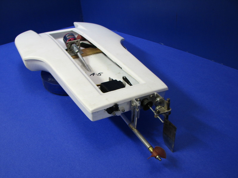
Will this do the trick? The mounting foot measures 5/16" x 1/2" and the rudder blade measures 1/32" x 3/4" x 2 1/2". The rudder will be 13/16" from the transom. I need to locate a proper fitting bellows type control rod seal yet but other than that I may make a few in the next week or so. I ordered a motor and esc from that place in China. Once that comes in I can start picking at a micro too.

Last edited by J Solinger; 06-20-2008 at 12:03 AM.
Fast Electric Addict!
So what do you figure these rudders would cost? I may just have to make another try on a 1/24th scale Hydro
Jim
"Our society strives to avoid any possibility of offending anyone except God.
Billy Graham
Senior Member
Fast Electric Addict!
Put me down for one
JIm
"Our society strives to avoid any possibility of offending anyone except God.
Billy Graham
Senior Member
Fast Electric Addict!
Joe,
Put me down for a few. At least 2, possibly 4. Once the laser-cut parts are finalized after this first build, I'll send you some if you would like.
Fast Electric Addict!
Joe,
Here is a thought I had: It looks like your design will allow the linkage to be on either side of the rudder by "flipping" the bracket and linkage arm (ball link shown). I prefer the servo linkage rod to be in tension for a right turn rather than compression. A long rod can flex when in compression. Will your proposed design allow for this?
Another thought or two: Could you put a radius on the upper leading edge of the rudder blade allowing it to "kick up" if it hits an obstacle? For the bellows, I have found an internal bellows works well when room is limited.
Last edited by Dr. Jet; 06-20-2008 at 03:15 PM. Reason: Add a second thought
Fast Electric Addict!
I have enough laser-cut parts for three prototype hulls coming in the mail, and they should arrive today or tomorrow. They may be on my doorstep when I get home from work today. I will quickly throw one set together and test-fit it into the hull. If I need to do any revisions to the CAD drawings, this will be the time.
The plan is to assemble the framework with thin CA, then paint the entire assembly with thinned epoxy to waterproof and secure all joints. After the water-proofing is done, the framework will be installed in the hull using expanding polyurethane glue. This stuff sticks anything together, fills gaps, floats, and probably improves your karma as well.
I will first glue the framework to the bottom hull half. After that has cured, I will install foam floatation in the sponsons with the PU glue. After that has cured, I will shape the foam to fit the deck, then I will apply a bead of PU glue to the top of the hull where it contacts the floatation, the framework, and where the two halves join. Then, while the glue is still liquid, I’ll tape the halves together, check for a square hull, then, leave the hull upside-down for the glue to expand and cure.
Once everything has cooked off, it will be time to cut the hatch open, mark the hull bottom for the stuffing tube, install the motor mount, stuffing tube and stuffing tube spine. As before, the wood assemblies will be assembled with CA, painted with epoxy, and installed in the hull with PU glue.
Hopefully, I will have a super-stiff, yet light hull at that point.
Senior Member
All the parts are symmetrical so you can flip and orient them any way you wish.Joe,
Here is a thought I had: It looks like your design will allow the linkage to be on either side of the rudder by "flipping" the bracket and linkage arm (ball link shown). I prefer the servo linkage rod to be in tension for a right turn rather than compression. A long rod can flex when in compression. Will your proposed design allow for this?
Yes, that should be fine.Another thought or two: Could you put a radius on the upper leading edge of the rudder blade allowing it to "kick up" if it hits an obstacle?
The internal rod seal will be the way to go.For the bellows, I have found an internal bellows works well when room is limited.
Fast Electric Addict!
Sounds like great changes
Jim
"Our society strives to avoid any possibility of offending anyone except God.
Billy Graham
Fast Electric Addict!
God, I love the smell of burnt wood!
I need to make the transom a bit narrower, and move the front cross-piece back a few thousandths, but overall, it fits. The changes can be made on the prototype framework with a file and some sandpaper, so all is well for the build from here on out.
Fast Electric Addict!
I jsut bought one of these Hydro's the other day.
Cant wait to start in on it.
Curious to see how that motor will work. Seems a bit small compared to Randy's suggestion?
 Posting Permissions
 |

 Reply With Quote
Bookmarks